SPONSORED LINKS
510 Series Troubleshooting
![]()
System Board and PCB Board Troubleshooting
Hard Disk Drive Troubleshooting
Internal Modem Troubleshooting
Chapter 2 describes how to determine if a Field Replaceable Unit
(FRU) in the computer is causing the computer to malfunction.
The FRUs covered are:
| 1. System (FVRSY*) Board | 7. Modem (FVRMD*) Board |
| 2. PCI (FR3PL*/PS*) Board | 8. Floppy Disk Drive |
| 3. Sound (FVRSD*) Board | 9. Hard Disk Drive |
| 4. CardBus (FVRCD*) Board | 10. CD-ROM Drive |
(only for 510CDS) |
|
| 6. DAA (FLXDA*) Board |
NOTE: The DAA (FLXDA*) Board is standard equipment in Canada and the United States and an option in Europe.
The Diagnostics Disk operations are described in Chapter 3 and detailed replacement procedures are given in Chapter 4.
The following tools are necessary for implementing the troubleshooting procedures:
1. Diagnostics Disk
2. Phillips screwdriver (2 mm)
NOTE: You must install the following onto the disk: SYS.COM, FORMAT.COM, FDISK.COM and FDISK.EXE
4. 2DD or 2HD formatted work disk for floppy disk drive testing
5. Cleaning kit for floppy disk drive troubleshooting
6. Printer port LED
7. Printer wraparound connector
8. Serial port wraparound connector
9. PC card wraparound card
10. Multimeter
11. External monitor
12. PS/2 or compatible keyboard
13. PS/2 or compatible mouse
14. Multimedia sound system with line-in and line-out ports
15. Headphone
16. Microphone
17. Speakers with amplifier
18. External FDD attachment
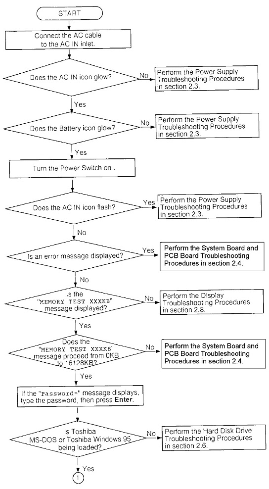
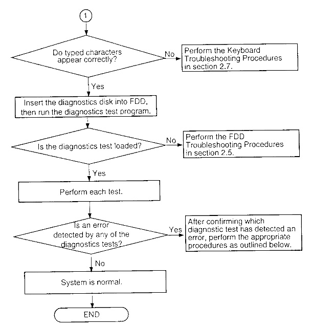
Use the flowchart in Figure 2-1 as a guide for determining which troubleshooting procedures to execute. Before going through the flowchart steps, do the following:
If the diagnostics program cannot detect an error, the problem may be intermittent. The Running Test program should be executed several times to isolate the problem.
Check the Log Utilities function to confirm which diagnostic test detected an error(s), then perform the appropriate troubleshooting procedures as follows:
The power supply controls many functions and components. To determine if the power supply is functioning properly, start with Procedure 1 and continue with the other procedures as instructed. The procedures described in this section are:
Procedure 1: Power Status Check
Procedure 2: Error Code Check
Procedure 3: Connection Check
Procedure 4: Quick Charge Check
Procedure 5: Replacement Check
Procedure 1 Power Status Check
The following icons indicate the power supply status:
 Battery icon (main battery
icon and second battery icon)
Battery icon (main battery
icon and second battery icon)
AC IN icon
The power supply controller displays the power supply status through the battery and the AC IN icons as shown in the tables below.
| Lights orange | Quick charge |
| Lights green | The battery has a full charge and the AC cable is connected. |
| Blinks orange
(even intervals) | The battery level becomes low while operating the computer on battery power.*1 |
| Flashes orange | The power switch is pressed on when the battery level is low.*2 |
| Doesn't light | Any condition other than those above. |
*1 AutoResume Off will be executed soon.
*2 AutoResume Off has already been executed.
| Lights green | DC power is being supplied from the AC PS unit or Desk Station V Plus. |
| Blinks orange | Power supply malfunction.*3 |
| Doesn't light | Any condition other than those above. |
*3 When the power supply controller detects a malfunction, the AC IN icon blinks and an error code is displayed.
To check the power supply status, install a battery pack and connect an AC PS unit.
| Check 1 | If the AC IN icon flashes orange, go to Procedure 2. |
| Check 2 | If the AC IN icon does not light, go to Procedure 3. |
| Check 3 | If the battery icon does not light orange or green, go to Procedure 4. |
Procedure 2 Error Code Check
If the microprocessor detects a malfunction, the AC IN icon blinks orange. The blink pattern indicates an error as shown below.
Start Off for 2 seconds
Error code (8 bit)
"1" On for one second
"0" On for half second
Interval between data bits Off for half second
An error code begins with the least significant digit.
Example: Error code 12h (Error codes are given in hexadecimal format.)
| Check 1 | Convert the AC IN icon blink pattern into the hexadecimal error code and compare it to the tables below. |
DC power is supplied through
the AC PS unit or Desk Station V Plus/Enhanced Port Replicator
II.
| AC PS unit output is over the maximum allowed limit. | |
| Desk Station V Plus output is over the maximum allowed limit. | |
| Current from the AC PS unit is over the maximum allowed limit. |
Battery pack
| Main battery voltage is over the maximum allowed limit. | |
| Main battery charge current is over the maximum allowed limit. | |
| Secondary battery voltage is over the maximum allowed limit. | |
| Secondary battery charge current is over the maximum allowed limit. |
B5V, VCC power supply output
| B5V voltage is over the maximum allowed limit. | |
| B5V voltage is below the minimum allowed limit. | |
| During suspend, B5V voltage is below the minimum allowed limit. |
B3V output
| B3V Voltage is over the maximum allowed limit. | |
| B3V Voltage is below the minimum allowed limit. | |
| B3V is below the minimum allowed limit during the suspend state. |
.
B12V Output
| B12V Voltage is over the maximum allowed limit. | |
| B12V Voltage is below the minimum allowed limit. |
.
Environmental condition
| CPU temperature is outside the allowable range. | |
| The CPU overheats, the system enters resume mode and automatically shuts down. |
| Check 2 | If error code 01h displays: |
Make sure the AC power cord
is firmly plugged into the AC inlet and wall outlet. If this cable
is connected correctly, go to the following step:
Make sure the AC PS unit cable
is firmly plugged into the DC In connector on the PCI board. If
this cable is connected correctly, go to the following step:
| Check 3 | If error code 02h displays: |
Make sure the Desk Station
V Plus is firmly connected to the computer's docking interface
port. If this port is connected correctly, go to the following
step:
Check the connector visually
to make sure no pins are bent. If a pin(s) is bent, go to Chapter
4, System board Replacement Procedures. If the connector
is not physically damaged, go to the following step:
Check the Desk Station V Plus
for malfunctions. Refer to the Desk Station V Plus maintenance
manual for details. If the error still exists, go to Procedure
5.
| Check 4 | If error code 10h or 14h displays: |
Make sure the battery pack
is correctly installed in the computer. If the battery pack is
correctly installed, go to the following step:
Replace the battery pack with
a new one. If the error still exists, go to Procedure 5.
| Check 5 | When 80h displays, it indicates that the CPU temperature is outside the allowable operating range. Perform the following steps: |
Leave the computer in an area
that is about room temperature until the CPU's internal temperature
is within the allowable operating range. If the error still exists,
go to Procedure 5.
| Check 6 | When 88h is displayed, it indicates that the CPU temperature is too high. When this occurs, the computer automatically enters resume mode and shuts down. |
Leave the computer off until
the AC IN icon stops blinking. It is recommended that you leave
the computer off until its interior reaches room temperature even
though the AC IN icon stops blinking.
| Check 7 | For any other error, go to Procedure 5. |
Procedure 3 Connection Check
The power supply wiring diagram is shown below:
Any of the connectors may be disconnected. Perform Check 1.
| Check 1 | Make sure the AC power cord is firmly plugged into the AC inlet and wall outlet. If the cable is connected correctly, go to Check 2. |
| Check 2 | If the AC IN icon does not glow green, go to Check 3. If the Battery icon does not glow orange, go to Check 4. |
| Check 3 | Make sure the AC PS unit cable is connected correctly to the PCI board at PJ501. If the cable is connected correctly, replace the AC PS unit. If the AC IN icon does not glow green, go to Procedure 5. |
| Check 4 | Make sure the battery pack is installed in the computer correctly. If the battery is properly installed and the Battery icon does not glow orange, go to Procedure 4. |
Procedure 4 Quick Charge Check
The power supply may not be charging the battery pack. Perform the following procedures:
1. Reinstall the battery pack and turn on the computer.
2. If the power does not come on, go to Procedure 5.
3. Run the Diagnostics test, select the System test, and execute subtest 06 (quick charge) as described in Chapter 3.
4. When the quick charge is complete, the Diagnostics test displays the result code. Check the result against the table below and perform any necessary check.
| The battery is quick charging normally. | Normal | |
| The battery is fully charged. | Normal | |
| The AC PS unit is not connected. | Check 2 | |
| The AC PS unit's output voltage is not normal. | Check 1 | |
| The battery is not installed. | Check 3 | |
| The battery's output voltage is not normal. | Check 4 | |
| The battery's temperature is not normal. | Check 5 | |
| A bad battery is installed. | Check 3 | |
| Any other problem. | Check 6 |
| Check 1 | Make sure the AC power cord is firmly plugged into the AC IN socket and wall outlet. If the cable is connected correctly, replace the AC power cord. |
| Check 2 | Make sure the AC PS unit cable is connected to PJ501 on the PCI board. If the cable is connected correctly, replace the AC PS unit. |
| Check 3 | Make sure the battery is properly installed. If it is properly installed, replace it with a new one. |
| Check 4 | The battery pack is completely discharged. Wait a few minutes to recharge it. If the battery pack still doesn't charge, replace it with a new one. |
| Check 5 | The battery's temperature is hot or cold. Return the battery to a normal operating condition. If the battery pack still doesn't charge, replace it with a new one. |
| Check 6 | Go to Procedure 5. |
Procedure 5 Replacement Check
The system board and PCI board may be disconnected or damaged. Disassemble the computer following the steps described in Chapter 4, Replacement Procedures, and check the connection between the PCI board and system board. If the boards are properly connected, perform the following checks:
| Check 1 | Replace the PCI board with a new one. If the PCI board is still not functioning properly, perform Check 2. |
| Check 2 | Replace the system board with a new one. |
This section describes how to determine if the system board or other PCB board is defective or not functioning properly. Start with Procedure 1 and continue with the other procedures as instructed. The procedures described in this section are:
Procedure 1: Message Check
Procedure 2: Printer Port LED Check on Boot Mode
Procedure 3: Printer Port LED Check on Resume Mode
Procedure 4: Diagnostic Test Program Execution Check
Procedure 5: Replacement Check
Procedure 1 Message Check
When the power is turned on, the system performs the Initial Reliability Test (IRT) installed in the BIOS ROM. The IRT tests each IC on the system board and initializes it.
If an error message is shown
on the display, perform Check 1.
If there is no error message,
go to Procedure 2.
| Check 1 | If any of the following error messages displays on the screen, press the F1 key as the message instructs. These errors occur when the system configuration preserved in the RTC memory (CMOS type memory) is not the same as the actual configuration or when the data is lost. |
| If you press the F1 key as the message instructs, the TSETUP screen appears to set the system configuration. If error message (b) appears often when the power is turned on, replace the RTC battery. If any other error message is displayed, perform Check 2. |
(a)                     *** Bad HDD type ***
                Check system.  Then press [F1] key ......
(b)                     *** Bad RTC battery ***
                Check system.  Then press [F1] key ......
(c)                     *** Bad configuration ***
                Check system.  Then press [F1] key ......
(d)                     *** Bad memory size ***
                Check system.  Then press [F1] key ......
(e)                     *** Bad time function ***
                Check system.  Then press [F1] key ......
(f)                     *** Bad check sum (CMOS) ***
                Check system.  Then press [F1] key ......
(g)             *** Bad check sum (ROM) ***
                Check system.  Then press [F1] key ......
| Check 2 | If the following error message is displayed on the screen, press any key as the message instructs.WARNING: RESUME FAILURE. PRESS ANY KEY TO CONTINUE. The error message appears when data stored in RAM under the resume function is lost because the battery has become discharged or the system board or PCI board is damaged. Go to Procedure 3. If any other message appears, perform Check 3. |
| Check 3 | The IRT checks the system board. When the IRT detects an error, the system stops or an error message appears. |
| If one of the following error messages (1) through (7), (9) through (17), (24) or (25) is displayed, replace the system board. | |
| If error message (8) is displayed, replace the PCI board. | |
| If error message (18) is displayed, go to the Keyboard Troubleshooting Procedures in Section 2.7. | |
| If error message (19), (20) or (21) is displayed, go to the HDD Troubleshooting Procedures in Section 2.6. | |
| If error message (22) or (23) is displayed, go to the FDD Troubleshooting Procedures in Section 2.5. |
(1) PIT ERROR
(2) MEMORY REFRESH ERROR
(3) TIMER CH.2 OUT ERROR
(4) CMOS CHECKSUM ERROR
(5)   CMOS BAD BATTERY ERROR
(6) FIRST 64KB MEMORY ERROR
(7) FIRST 64KB MEMORY PARITY ERROR
(8) VRAM ERROR
(9) SYSTEM MEMORY ERROR
(10) SYSTEM MEMORY PARITY ERROR
(11) EXTENDED MEMORY ERROR
(12) EXTENDED MEMORY PARITY ERROR
(13) DMA PAGE REGISTER ERROR
(14) DMAC #1 ERROR
(15) DMAC #2 ERROR
(16)    PIC #1 ERROR
(17)    PIC #2 ERROR
(18)    KBC ERROR
(19)    HDC ERROR
(20)    HDD #0 ERROR
(21)    HDD #1 ERROR
(22)    NO FDD ERROR
(23)    FDC ERROR
(24)    TIMER INTERRUPT ERROR
(25)    RTC UPDATE ERROR
Procedure 2 Printer Port LED Check on Boot Mode
The printer port LED displays the IRT status and test status by turning lights on and off as an eight-digit binary value for boot mode. Figure 2-2 shows the printer port LED.
 Figure
2-2 Printer port LED
Figure
2-2 Printer port LEDTo use the printer port LED follow these steps:
1. Make sure the computer is in boot mode.
2. Plug the printer port LED into the computer's parallel port.
3. Turn on the computer's power.
4. Read the LED status from left to right as you are facing the back of the computer.
5. Convert the status from binary to hexadecimal notation.
6. If the final LED status is FFh (normal status), go to Procedure 3.
7. If the final LED status matches any of the test status values in Table 2-3, perform Check 1.
NOTE: If an error condition is detected by the IRT test, the printer port LED displays an error code after the IRT test ends. For example, when the printer port LED displays 1F and halts, the IRT test has already completed the Display initialization. In this instance, the IRT indicates an error has been detected during the system memory test.
| Special register initialization | ||
| PIT test | PIT ERROR | |
| PIT initialization | - | |
| PIT function check | MEMORY REFRESH ERROR
TIMER CH.2 OUT ERROR | |
| CMOS check | CMOS CHECKSUM ERROR CMOS BAD BATTERY ERROR | |
| Initialization of memory configuration | - | |
| SM-RAM check | - | |
| ROM/RAM copy | - | |
| Selftest skip check | - | |
| Initialization of internal VGA | - | |
| System check | - | |
| First 64 KB memory test | FIRST 64KB MEMORY ERROR
FIRST 64KB MEMORY PARITY ERROR | |
| System memory initialization | - | |
| System initialization | - | |
| Interrupt vector initialization | - | |
| PIC initialization | - | |
| Display initialization | VRAM ERROR | |
| System memory test | SYSTEM MEMORY ERROR
SYSTEM MEMORY PARITY ERROR | |
| Extended memory test | EXTENDED MEMORY ERROR EXTENDED MEMORY PARITY ERROR | |
| DMA page register test | DMA PAGE REGISTER ERROR | |
| DMAC test | DMAC #X ERROR | |
| DMAC initialization | - | |
| PIC test | PIC #X ERROR | |
| Mouse initialization | - | |
| KBC initialization | KBC ERROR | |
| Boot password | - | |
| HDD initialization | HDC ERROR/HDD #0 ERROR | |
| FDD initialization | FDC ERROR/NO FDD ERROR |
| Printer initialization | - | |
| SIO initialization | - | |
| Timer initialization | RTC UPDATE ERROR
TIMER INTERRUPT ERROR | |
| NDP initialization | - | |
| Initialization of expansion ROM | - | |
| Password check | - | |
| Setup boot check | Check system. Then press [F1] key. | |
| Boot load | - |
| Check 1 | If any of the following error codes are displayed, go to Procedure 5. 00h, 01h, 02h, 03h, 04h, 05h, 06h, 07h, 08h, 09h, 0Ah, 0Bh, 0Ch, 0Dh, 18h, 1Fh, 25h, 30h, 40h, 41h, 42h, 4Ah, 55H, 65h, 70h, 80h, 90h, A0H, A6h, C0h, Feh |
| Check 2 | If error code 50h is displayed, go to the Keyboard Troubleshooting procedures in Section 2.7. |
| Check 3 | If error code 5Ah is displayed, go to the HDD Troubleshooting Procedures in Section 2.6. |
| Check 4 | If error code 60h is displayed, go to the FDD Troubleshooting Procedures in Section 2.5. |
Procedure 3 Printer Port LED Check on Resume Mode
The printer port LED displays the IRT status and test status by turning lights on and off as an eight-digit binary value for resume mode.
To use the printer port LED, follow these steps:
1. Make sure the computer is in resume mode.
2. Plug the printer port LED into the computer's parallel port.
3. Turn on the computer's power.
4. Read the LED status from left to right as you face the back of the computer.
5. Convert the status from binary to hexadecimal notation.
6. If the final LED status is FFh (normal status), go to Procedure 4.
7. If the final LED status matches any of the test status values in Table 2-4, perform Procedure 5.
| System BIOS RAM checksum error | |
| External display card is connected | |
| HDD was installed | |
| SMRAM checksum error or memory error during suspend | |
| Conventional memory checksum error | |
| Video RAM checksum error | |
| Extended memory checksum error | |
| PnP RAM checksum error |
Procedure 4 Diagnostic Test Program Execution Check
Execute the following tests from the Diagnostic Test Menu. Refer to Chapter 3, Tests and Diagnostics, for more information on how to perform these tests.
1. System test
2. Memory test
3. Printer test
4. ASYNC test
5. Real Timer test
6. Expansion test
7. Sound test
8. Modem test
If an error is detected during any of these tests, go to Procedure 5.
Procedure 5 Replacement Check
The system board or another PCB may be damaged. Disassemble the computer following the steps described in Chapter 4, Replacement Procedures, and perform the following checks:
If any of the following diagnostic tests detects an error, go to Check 1.
If the Sound test detects an error, go to Check 2.
If the Modem test detects an error, go to Check 5
NOTE: Refer to Chapter 4 for instructions on how to remove and replace any of the following items.
| Check 1 | Replace the system board with a new one. If the problem still exists, go to Check 6. |
| Check 2 | Replace the sound board with a new one. If the problem still exists, go to Check 3. |
| Check 3 | Replace the flat cable with a new one. If the problem still exists, go to Check 6. |
| Check 4 | Replace the DAA board with a new one. If the problem still exists, go to Check 5. |
| Check 5 | Replace the modem board with a new one. If the problem still exists, go to Check 6. |
| Check 6 | Replace the PCI board with a new one. |
This section describes how to determine if the FDD is functioning properly. Perform the steps below starting with Procedure 1 and continuing with the other procedures as required.
Procedure 1: FDD Head Cleaning Check
Procedure 2: Diagnostic Test Program Execution Check
Procedure 3: Connector Check and Replacement Check
Procedure 1 FDD Head Cleaning Check
FDD head cleaning is one option available in the Diagnostic Program. Detailed operation is given in chapter 3, Tests and Diagnostics.
Insert the diagnostics disk in the computer's floppy disk drive, turn on the computer, run the test, and then clean the FDD heads using the cleaning kit. If the FDD still does not function properly after cleaning, go to Procedure 3.
If the test program cannot be executed on the computer, go to Procedure 3.
Procedure 2 Diagnostic Test Program Execution Check
Insert the diagnostics disk in the FDD, turn on the computer, and run the test. Refer to Chapter 3, Tests and Diagnostics, for more information about the diagnostics test procedures.
Floppy disk drive test error codes and their status names are described in Table 2-5. Make sure the floppy disk in the FDD is formatted correctly and that the write protect tab is disabled. If any other errors occur while executing the FDD diagnostics test, go to Check 1.
| Bad command | |
| Address mark not found | |
| Write protected | |
| Record not found | |
| Media removed on dual attach card | |
| DMA overrun error | |
| DMA boundary error | |
| CRC error | |
| FDC error | |
| Seek error | |
| FDD not in drive | |
| Time out error (Not ready) | |
| Write buffer error | |
| Data compare error |
| Check 1 | If the following message is displayed, disable the write protect tab on the floppy disk. Write protected If any other message appears, perform Check 2. |
| Check 2 | Make sure the floppy disk is formatted correctly. If it is, go to Procedure 3. |
Procedure 3 Connector Check and Replacement Check
There are two ways to connect the FDD: through the selectable bay and through the external FDD port. If the FDD is installed in the selectable bay, begin with Check 1 below. If the FDD is connected to the external FDD port, begin with Check 3.
| Check 1 | Make sure the selectable bay is firmly connected to the FDD module and system board. |
If any of the connections are loose, reconnect firmly and repeat Procedure 2. If there is still an error, go to Check 2.
| Check 2 | The sound board may be defective or damaged. Replace the sound board. If the FDD is still not functioning properly, perform Check 4. |
| Check 3 | Make sure the FDD cable is firmly connected to the external FDD port. |
| If this cable is disconnected, connect it to the system unit and repeat Procedure 2. If the FDD is still not functioning properly, perform Check 4. | |
| Check 4 | The flexible cable may be defective or damaged. Replace the flexible cable with a new one following the steps in Chapter 4, Replacement Procedures. If the FDD is still not functioning properly, perform Check 5. |
| Check 5 | The FDD may be defective or damaged. Replace the FDD with a new one following the steps in Chapter 4. If the FDD is still not functioning properly, perform Check 6. |
| Check 6 | Replace the system board with a new one following the steps in Chapter 4. |
To determine if the hard disk drive is functioning properly, perform the procedures below starting with Procedure 1. Continue with the other procedures as instructed.
Procedure 1: Partition Check
Procedure 2: Message Check
Procedure 3: Format Check
Procedure 4: Diagnostic Test Program Execution Check
NOTE:
The contents of the hard disk will be erased when the HDD troubleshooting procedures are executed. Transfer the contents of the hard disk to floppy disk or other device. If the customer has not or cannot perform the back-up, create back-up disks as listed below.
Refer to the appropriate instructions for each operating system.
Insert the Toshiba MS-DOS system disk, turn on the computer, and perform the following checks:
| Check 1 | Type C: and press Enter. If you cannot change to drive C, go to Check 2. If you can change to drive C, go to Procedure 2. |
| Check 2 | Type FDISK and press Enter. Choose Display Partition Information from the FDISK menu. If drive C is listed, go to Check 3. If drive C is not listed, return to the FDISK menu and choose the option to create a DOS partition on drive C. Recheck the system. If the problem still exists, go to Procedure 2. |
| Check 3 | If drive C is listed as active in the FDISK menu, go to Check 4. If drive C is not listed as active, return to the FDISK menu and choose the option to set the active partition for drive C. Recheck the system. If the problem still exists, go to Procedure 2. |
| Check 4 | Remove the system disk from the FDD and cold boot the computer. If the problem still exists, go to Procedure 2. Otherwise, the HDD is operating normally. |
When the computer's HDD does not function properly, some of the following error messages may appear on the display. Start with Check 1 below and perform the other checks as instructed.
| Check 1 | If any of the following messages appear, perform Check 5.HDC ERROR (After 5 seconds this message will disappear.) or HDD #0 ERROR (After 5 seconds this message will disappear.) or HDD #1 ERROR (After 5 seconds this message will disappear.) If the above messages do not appear, perform Check 2. |
| Check 2 | If either of the following messages appears, perform Check 3.Insert system disk in drive Press any key when ready ..... or Non-System disk or disk error Replace and press any key If the above messages do not appear, perform Check 5. |
| Check 3 | Check TSETUP to see whether the Hard Disk option is set to Not used. If it is set to Not used, choose another setting and repeat Check 1. If it is not set to Not used, go to Check 4. |
| Check 4 | Using the Toshiba MS-DOS system disk, install a system program on the hard disk using the SYS command. If the following message appears on the display, the system program has been transferred to the HDD. Restart the computer. If the error message still appears, perform Check 5. System transferred |
| Check 5 | The HDD is connected to the flexible cable and the system board. The flexible cable can become disconnected or damaged. Disassemble the computer as described in Chapter 4, Replacement Procedures. If the HDD is not firmly connected, connect it to the flexible cable and return to Procedure 1. If the HDD is firmly connected to the system board, perform Check 6. |
| Check 6 | The HDD connector may be defective or damaged. Replace the HDD connector with a new one following the steps in Chapter 4, Replacement Procedures. If the HDD is still not functioning properly, perform Procedure 3. |
The computer's HDD is formatted using the low level format program and the MS-DOS FORMAT program. To format the HDD, start with Check 1 below and perform the other checks as required.
| Check 1 | Using the Toshiba MS-DOS system disk, partition the hard disk using the FDISK command. Format the hard disk using FORMAT C:/S/U to transfer the system program to the HDD. If the following message appears on the display, the HDD is formatted.
Format complete If any other error message appears on the display, refer to the Toshiba MS-DOS Manual for more information and perform Check 2. |
| Check 2 | Using the diagnostics disk, format the HDD with a low level format option. Refer to Chapter 3, Tests and Diagnostics, for more information about the diagnostic program.
If the following message appears on the display, the HDD low level format is complete. Partition and format the HDD using the MS-DOS FORMAT command. Format complete If you cannot format the HDD using the tests and diagnostics program, go to Procedure 4. |
Procedure 4 Diagnostic Test Program Execution Check
The HDD test program is stored in the diagnostics disk. Perform all of the HDD tests in the Hard Disk Drive Test. Refer to Chapter 3, Tests and Diagnostics, for more information about the HDD test program.
If an error is detected during the HDD test, an error code and status will display; perform Check 1. The error codes and statuses are listed in Table 2-6. If an error code is not generated, the HDD is operating properly.
| Bad command | |
| Bad address mark | |
| Record not found | |
| HDC not reset | |
| Drive not initialized | |
| HDC overrun (DRQ) | |
| DMA boundary error | |
| Bad sector error | |
| Bad track error | |
| ECC error | |
| ECC recover enabled | |
| HDC error | |
| Seek error | |
| Time out error | |
| Drive not ready | |
| Undefined error | |
| Write fault | |
| Status error | |
| Access time out error | |
| Data compare error | |
| Check 1 | Replace the HDD unit with a new one following the instructions in Chapter 4, Replacement Procedures. If the HDD is not functioning properly, perform
Check 2. |
| Check 2 | Replace the flexible cable with a new one following the instructions in Chapter 4. |
| Check 3 | Replace the system board with a new one following the instructions in Chapter 4. |
To determine if the computer's keyboard is functioning properly, perform the following procedures. Start with Procedure 1 and continue with the other procedure as instructed.
Procedure 1: Diagnostic Test Program Execution Check
Procedure 2: Connector and Replacement Check
Procedure 1 Diagnostic Test Program Execution Check
Execute the Keyboard Test in the Diagnostic Program. Refer to Chapter 3, Tests and Diagnostics, for more information on how to perform the test program.
If an error occurs, go to Procedure 2. If an error does not occur, the keyboard is functioning properly.
Procedure 2 Connector and Replacement Check
The keyboard is connected to the sound board by a flat cable, and the sound board is connected to the system board. This cable or connector may be disconnected or damaged. Disassemble the computer as described in Chapter 4, Replacement Procedures, and perform the following checks:
| Check 1 | Make sure the keyboard cable is not damaged and is connected to the sound board. |
| Check 2 | The sound board may be damaged. Replace the sound board with a new one. Refer to Chapter 4 for more information. |
| Check 3 | The system board may be damaged. Replace the system board with a new one. Refer to Chapter 4 for more information. |
This section describes how to determine if the computer's display is functioning properly. Start with Procedure 1 and continue with the other procedures as instructed.
Procedure 1: External Monitor Check
Procedure 2: Diagnostic Test Program Execution Check
Procedure 3: Connector Check
Procedure 4: Replacement Check
Procedure 1 External Monitor Check
Connect the external monitor to the computer's external monitor port, then boot the computer.
If the external monitor works correctly, the internal LCD display may be damaged. Go to Procedure 3.
If the external monitor appears to have the same problem as the internal LCD, the display controller may be damaged. Go to Procedure 2.
Procedure 2 Diagnostic Test Program Execution Check
The Display Test program is stored on the diagnostics disk. This program checks the display controller on the PCI board. Insert the Diagnostics disk in the computer's floppy disk drive, turn on the computer, and run the test. Refer to Chapter 3, Tests and Diagnostics, for details.
If an error is detected, go to Procedure 3. If an error is not detected, the display is functioning properly.
The display unit has an LCD module, FL, display switch, and FL inverter board. The FL and FL inverter board are connected by two cables at CN2. The LCD module and PCI board are connected by one signal cable (PJ2) as shown below. Any of these cables may be disconnected.
Disassemble the display unit and check the following cable connections. Refer to Chapter 4. Replacement Procedures, for more information about how to disassemble the computer.
 Figure
2-3 Display connection
Figure
2-3 Display connectionThe FL, FL inverter board, LCD module, and PCI board are connected to the display circuits. Any of these components may be damaged. Refer to Chapter 4, Replacement Procedures, for instructions on how to disassemble the computer and then perform the following checks:
| Check 1 | Replace the FL inverter board with a new one and test the display again. If the problem still exists, perform Check 2. |
| Check 2 | Replace the FL with a new one and test the display again. If the problem still exists, perform Check 3. |
| Check 3 | Replace the LCD module with a new one and test the display again. If the problem still exists, perform Check 5. |
| Check 4 | Replace the display switch with a new one and test the display again. If the problem still exists, perform Check 5. |
| Check 5 | Replace the display cable with a new one and test the display again. If the problem still exists, perform Check 6. |
| Check 6 | The PCI board may be damaged. Replace the PCI board with a new one. |
This section describes how to determine if the computer's internal CD-ROM drive is functioning properly. Perform the steps below starting with Procedure 1 and continuing with the other procedures as required.
Procedure 1: CD Cleaning Check
Procedure 2: Diagnostic Test Program Execution Check
Procedure 3: Connector Check and Replacement Check
1. Turn off the power.
2. Open the CD drawer by inserting a slender object, such as a straightened paper clip, into the eject hole. The object must be long enough to activate the eject mechanism.
3. Clean the laser pickup lens with a lens cleaner. Apply the cleaner to a cloth and wipe the lens.
4. If the CD-ROM drive does not function properly after cleaning,
go to
Procedure 2.
Procedure 2 Diagnostic Test Program Execution Check
The CD-ROM drive Diagnostic test program is stored on the diagnostics disk. Insert a test CD (Toshiba-EMI Test Disc TDY-03) into the CD-ROM drive. Next, insert the diagnostics disk into the computer's floppy disk drive, turn on the computer, and run the test. Refer to Chapter 3, Tests and Diagnostics, for more information about the diagnostics test procedures.
If any other errors occur while executing the CD-ROM drive diagnostics test, go to Procedure 3.
Procedure 3 Connector Check and Replacement Check
The CD-ROM drive is connected to the sound board and flexible cable by the CD-ROM drive cable. This cable may be disconnected from the sound board or the flexible cable may be damaged. Disassemble the computer following the steps listed in Chapter 4, Replacement Procedures, and perform the following checks:
| Check 1 | Make sure the selectable bay cable is firmly connected to the CD-ROM drive and the sound board. |

If any of the connections are loose, reconnect firmly and repeat Procedure 2. If there is still an error, go to Check 2.
| Check 2 | Replace the flexible cable with a new one following the steps in Chapter 4. If the CD-ROM drive is still not functioning properly, perform Check 3. |
| Check 3 | The CD-ROM drive may be defective or damaged. Replace the CD-ROM drive with a new one following the steps in Chapter 4. If the CD-ROM drive is still not functioning properly, perform Check 4. |
| Check 4 | Replace the sound board with a new one following the steps in Chapter 4. If the CD-ROM drive is still not functioning properly, perform Check 5. |
| Check 5 | Replace the system board with a new one following the steps in Chapter 4. |
This section describes how to determine if the internal modem is functioning properly. Perform the steps below starting with Procedure 1 and continuing with the other procedure as required.
Procedure 1: Diagnostic Test Program Execution Check
Procedure 2: Connector Check and Replacement Check
Procedure 1 Diagnostic Test Program Execution Check
The internal modem Diagnostic test program is stored on the diagnostics disk. This program checks the internal modem. Insert the diagnostics disk in the computer's floppy disk drive, turn on the computer, and run the test. Refer to Chapter 3, Tests and Diagnostics, for details.
| Check 1 | Execute modem subtest 1. If an error occurs, the modem board may be malfunctioning. Replace the modem board. If errors still occur, go to Check 2. |
| Check 2 | Execute modem subtest 2. If an error occurs, the DAA module may be malfunctioning. Replace the DAA module. If errors still occur, go to Check 3. |
| Check 3 | Execute modem subtests 3 and 4. If an error occurs, the modem board and DAA module or the speakers may be malfunctioning. Replace the modem board and the DAA module or the speakers. |
If any other errors occur while executing the internal modem diagnostics Test, go to Procedure 2.
Procedure 2 Connector Check and Replacement Check
The DAA board is connected to the modem board. If the modem malfunctions, there may be a bad connection between the DAA board and the modem board or between the modem board and the PCI board. Also, the DAA module, modem board, or PCI board may be damaged.
Disassemble the computer following the steps in Chapter 4, Replacement Procedures, and perform the following checks:
| Check 1 | Make sure PJ1 on the DAA board is firmly connected to PJ602 on the modem board and that PJ601 on the modem board is firmly connected to PJ6 on the PCI board. |

| Check 2 | The DAA board may be defective or damaged. Replace the DAA board with a new one following the steps in Chapter 4. If the DAA board is still not functioning properly, perform Check 3. |
| Check 3 | Replace the modem board with a new one following the steps in Chapter 4. If the DAA board is still not functioning properly, perform Check 4. |
| Check 4 | Replace the PCI board with a new one following the steps in Chapter 4. |