A little while ago, this power supply that I purchased in 2011 blew up and in doing so, tripped the building breaker it was connected to through the APC Smart-UPS 1000 it was connected to. With a little work, I was able to repair it.
There were some mistakes in the design, resulting in what appears to be planned obsolescence judging from the recent barrage of customer reviews complaining about failures, but this series of OCZ power supplies (including 500W, 600W and 700W units) are of reasonable quality (using presumably authentic Teapo capacitors, with the exception of the questionable main filter capacitor) and should last quite a few more years.
This repair diary including partial schematic and this message board thread give the basic background on the failure mode and repair. If your model is one which has an internal fuse like mine, you are probably in luck as the blown fuse prevented further damage. Otherwise, you have more components to check and likely more work to do.
Step 1: Check components
The following components are likely bad. Test as described and replace if suspect.
1. “Teapo”400V 390uF input filter capacitor. Top was slightly bulging and ESR tested high. As this particular capacitor was known to be a problem, I did not test it further. I replaced it with a much nicer Nichicon 450V 390uF 105 degree capacitor, which was a little taller but fit nicely.
2. Infineon 20N60C3 power MOSFET (or other equivalent) in the input stage. On the AC side of the power supply, just look for the large heatsink with multiple two and three-legged components and test them all. A bad MOSFET will show a low resistance close to zero in both directions. I replaced this with an (obsolete) Farnell FCA20N60. Any 20N60 MOSFET should work if the package fits and the voltage rating is sufficient.
3. Power Integrations TNY278PN switch mode IC near transformers. It has 7 legs and a diode between two legs on the solder side of the PCB. A leg was blown off in my unit, and it flamed out and cracked off part of the plastic package. I replaced this with a TNY278PG. I wasn’t sure about the difference, but it worked.
4. Generic T10AH250V (10A 250V) 5x20mm slow-blow fuse. Buy multiple fuses since you might need more than one try to catch everything.
Cost of parts: about $18 before shipping. The capacitor was the most expensive at $9; one could reasonably choose a less nice (and much cheaper) one as a functional equivalent.
Step 2: Replace components
To get access to the solder side, just remove the 4 screws attaching the main PCB to the case, and then bend the side of the case where the AC plug is mounted out of the way until you get enough clearance to pull the main PCB out somewhat. In this position you can do all the work without having to disconnect anything more.
General desoldering technique used: heat the old joint, add fresh 60/40 solder, use a spring-loaded solder sucker to clear the joint, and repeat as necessary until the component is removable, or at least removable with a brief touch of the soldering iron tip.
Once the old component is removed, clear the through-hole completely continuing the same technique. It can help to heat the through-hole, add new solder, and move the leg of a component in and out of and around the hole to distribute the flux to any stubborn old solder.
1. The capacitor just needs to be desoldered and replaced.
2. The MOSFET unfortunately cannot be replaced without desoldering the entire input stage (everything attached to the heatsink next to the main capacitor). When screwing the new MOSFET to the heatsink, ensure that you use a thin film of heatsink compound. And don’t lose or forget to reinstall the small choke around the MOSFET leg.
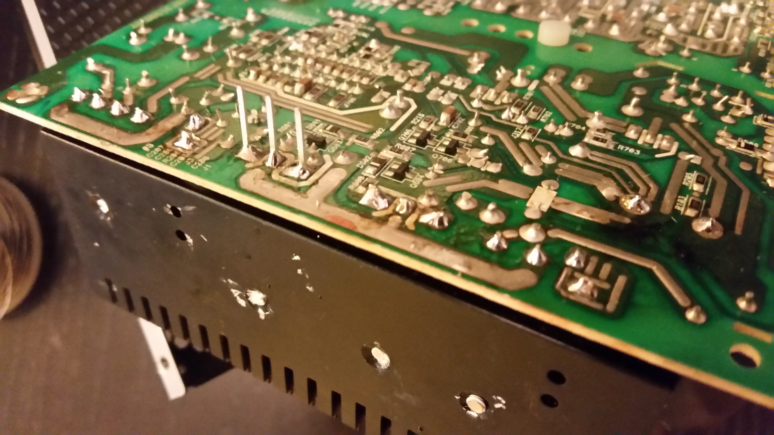
Here is a picture of the reinstalled input stage waiting for the leads on the new MOSFET to be clipped:
3. The switching IC just needs to be desoldered and replaced. When you install the new IC, you probably have to clip a very small length off the legs before installing so that it will fit back into place without having to remove the large heatsink that overhangs its location. Also, since this IC is not heatsinked, avoid heating the legs for any longer than necessary and pause between soldering each leg.
4. The fuse just needs to be desoldered and replaced, taking care to install a piece of heat shrink tubing on the exposed leg to protect against potential contact shorts.
Step 3: Test
You can do some tests before reassembling. Beware that the main capacitor carries a large charge and could be dangerous for some time after being connected to AC, so if you need to revisit the circuit after testing, to be safe wait a bit and then check the capacitor is discharged by touching its leads together with an insulated metal object, such as a screwdriver.
1. Screw the main PCB into the case with 4 screws, connect the case top with fan to the 2-wire plug, carefully connect AC power to the input connector, and flip the PSU main switch on. If the fuse instantly blows, you likely have more shorted components in the INPUT stage to diagnose.
2. If the fuse doesn’t blow, check the ATX +5VSB pin (purple wire) for 5VDC and the PS_ON pin (green wire) for something like 5VDC. If these are not present, then there is some problem in the switching circuit or possibly the output capacitors.
3. If the correct voltages are present at the output, use a piece of wire to short the PS_ON pin (green wire) to ground (one of the adjacent black wires). The fan should begin to spin. If you hook up a hard disk or other peripheral, it should function.
If the above was successful, you can consider the repair a success and reinstall the power supply. Enjoy!
our model is one which has an internal fuse like mine, you are probably in luck as the blown fuse prevented further damage. Otherwise, you have more components to check and likely more work to do.
Step 1: Check components
The following components are likely bad. Test as described and replace if suspect.
1. “Teapo” 400V 390uF input filter capacitor. Top was slightly bulging and ESR tested high. As this particular capacitor was known to be a problem, I did not test it further. I replaced it with a much nicer Nichicon 450V 390uF 105 degree capacitor, which was a little taller but fit nicely.
2. Infineon 20N60C3 power MOSFET (or other equivalent) in the input stage. On the AC side of the power supply, just look for the large heatsink with multiple two and three-legged components and test them all. A bad MOSFET will show a low resistance close to zero in both directions. I replaced this with an (obsolete) Farnell FCA20N60. Any 20N60 MOSFET should work if the package fits and the voltage rating is sufficient.
3. Power Integrations TNY278PN switch mode IC near transformers. It has 7 legs and a diode between two legs on the solder side of the PCB. A leg was blown off in my unit, and it flamed out and cracked off part of the plastic package. I replaced this with a TNY278PG. I wasn’t sure about the difference, but it worked.
4. Generic T10AH250V (10A 250V) 5x20mm slow-blow fuse. Buy multiple fuses since you might need more than one try to catch everything.
Cost of parts: about $18 before shipping. The capacitor was the most expensive at $9; one could reasonably choose a less nice (and much cheaper) one as a functional equivalent.
Step 2: Replace components
To get access to the solder side, just remove the 4 screws attaching the main PCB to the case, and then bend the side of the case where the AC plug is mounted out of the way until you get enough clearance to pull the main PCB out somewhat. In this position you can do all the work without having to disconnect anything more.
General desoldering technique used: heat the old joint, add fresh 60/40 solder, use a spring-loaded solder sucker to clear the joint, and repeat as necessary until the component is removable, or at least removable with a brief touch of the soldering iron tip.
Once the old component is removed, clear the through-hole completely continuing the same technique. It can help to heat the through-hole, add new solder, and move the leg of a component in and out of and around the hole to distribute the flux to any stubborn old solder.
1. The capacitor just needs to be desoldered and replaced.
2. The MOSFET unfortunately cannot be replaced without desoldering the entire input stage (everything attached to the heatsink next to the main capacitor). When screwing the new MOSFET to the heatsink, ensure that you use a thin film of heatsink compound. And don’t lose or forget to reinstall the small choke around the MOSFET leg.
Here is a picture of the reinstalled input stage waiting for the leads on the new MOSFET to be clipped:
3. The switching IC just needs to be desoldered and replaced. When you install the new IC, you probably have to clip a very small length off the legs before installing so that it will fit back into place without having to remove the large heatsink that overhangs its location. Also, since this IC is not heatsinked, avoid heating the legs for any longer than necessary and pause between soldering each leg.
4. The fuse just needs to be desoldered and replaced, taking care to install a piece of heat shrink tubing on the exposed leg to protect against potential contact shorts.
Step 3: Test
You can do some tests before reassembling. Beware that the main capacitor carries a large charge and could be dangerous for some time after being connected to AC, so to be safe, wait a bit and then check it is discharged by touching the leads together with an insulated metal object, such as a screwdriver.
1. Screw the main PCB into the case with 4 screws, connect the case top with fan to the 2-wire plug, and carefully connect AC power to the input connector. If the fuse instantly blows, you likely have more shorted components in the INPUT stage to diagnose.
2. If the fuse doesn’t blow, check the ATX +5VSB pin (purple wire) for 5VDC and the PS_ON pin (green wire) for something like 5VDC. If these are not present, then there is some problem in the switching circuit or possibly the output capacitors.
3. If the correct voltages are present at the output, use a piece of wire to short the PS_ON pin (green wire) to ground (one of the adjacent black wires). The fan should begin to spin. If you hook up a hard disk or other peripheral, it should function.
If the above was successful, you can consider the repair a success and reinstall the power supply. Enjoy!