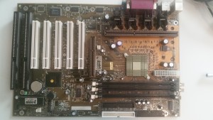
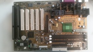
This Athlon motherboard was suffering from a leaked 1000uF 10V “Chhsi” capacitor, part of the Taiwanese capacitor plague, and the system was experiencing instability, so I decided to replace it. As usual, when replacing one failed capacitor of a manufacturer and vintage, I sought to replace all such capacitors on this board. However, the end result of this process was a short circuit that caused an IR S14410 power MOSFET near the CPU slot to shoot flames on powerup. What happened?
I found that in (sloppily) replacing a 220uF electrolytic capacitor next to the CPU socket, the via for its negative leg, which is connected to the output of a EZ1580CM adjustable linear voltage regulator, had become connected to the PCB ground plane. Since the PCB is a 6 layer PCB due to design difficulties with the early AMD Irongate Athlon chipset, such erroneous connections between layers are more probable than usual. This resulted in a dead short from both the regulator and the MOSFET drain to source! The regulator got hot enough to fry, but survived, but the MOSFET smoked immediately.
To note, I have both a rev 1.0 and rev 1.0B of this motherboard (pics below; the rev 1.0 has been recapped already). Both are silk-screened “MS6167 VER:1” in large print, but can actually be distinguished by silk screen at the edge between the CPU slot and RAM; the rev 1.0 reads “16167-100” while the rev 1.0B reads “16167-10B”. There are a few differences, but notably, the EZ1580CM regulator located directly underneath the CPU heatsink has been removed, replaced with a LX8384 part, and relocated to the PCI slot area. I don’t understand exactly what this circuit does; it seems to exist to stabilize the 3.3V rail.
Enough rambling, so how do we fix this mess, a short circuit between PCB layers? Well, there are probably a few ways, but after carefully studying the situation and comparing voltages and impedances at various points with the known good board, here’s what I did:
- Removed the (new) 220uF capacitor.
- Drilled out the via causing the short circuit, first with a 1/16″ bit, and when that proved insufficient to clear the short, a 5/64″ bit.
- Once the short was cleared, using hot air I removed the blown MOSFET and added a great deal of solder to the “tab” of the EZ1580CM. The tab carries the output voltage and heatsinks the regulator to the board. By heating up this IC and adding a blob of solder to the top of the tab, I created a connection point for the capacitor leg.
- I then soldered a new 220uF capacitor back in, connecting the leg that would have gone through the (now non-existent) via to the solder blob at the top of the EZ1580CM.
- After a quick check for soldering shorts, I applied power and ensured that the output voltage of the EZ1580CM looked sane (and that the IC was no longer frying). It was about 3.5V. I checked that this voltage was present at the MOSFET source pads.
- I installed a new IR S14410 MOSFET using hot air.
- I powered on the system and it began to act normally again. Success!
This is a lesson in how things can go wrong when I extend my mission to “preventative maintenance” instead of being satisfied with just fixing what’s broke.

