Having a Linux distribution installed on an Android netbook can be the best of both worlds. Leveraging the Linux kernel already running on any Android device, a Linux userspace will be native and fast and come with many tools power users will appreciate. Here are some ways to get the most out of the Linux on Android experience.
APC AP9584 USB Conversion Kit and APC Serial Smart-UPS
April 26th, 2017The AP9584 serial-to-USB conversion kit for older APC UPS models with a serial host interface is the manufacturer-endorsed solution for interfacing such older UPS units with a USB-based host computer. However, it is specified on the label for “use with APC Back-UPS and Back-UPS Pro only”. Will it work with a Smart-UPS unit?
Initially, it would seem so – all the variables are read properly. However, after a period of 30 days or so, and generally unnoticed to the operator, the “LB” (Low Battery”) status flag is flipped on, while nothing is actually wrong with the battery. This does not cause an immediate problem. However, the next time the UPS does a periodic self-test, the “OB” (“On Battery”) status flag will be temporarily set as is expected during a self-test cycle. However, from the perspective of UPS monitoring software, the combination of LB and OB means “The UPS is nearly dead, so shut down the system cleanly”. As a result, every system listening to the UPS monitoring software would immediately (and cleanly) shut down, and then dutifully wait for a UPS power-cycle that never came!
- I thought at first this was an anomaly with the particular UPS (Smart-UPS 1500), so I switched to a Smart-UPS 1000. Same result.
- I thought then that I had just gotten a defective cable, and bought another AP9584 to test. Same result.
- I then replaced the AP9584 with a good old APC 940-0024C and a Kawamall USB to DB9 (male) serial converter. After months, the problem never happened again!
The Kawamall USB to serial converter has USB vendor:device 1a86:7523 corresponding to a QinHeng Electronics HL-340. Others have noted that Prolific converters also seem to work.
In any case, don’t bother trying to use the APC AP9584 on a Smart-UPS – there seems to be a bug that will cause your systems to be powered off unexpectedly. Just use a normal USB-to-serial converter with the APC 940-0024C or similar smart monitoring cable.
ACPI Warning: SystemIO range X conflicts with OpRegion Y error
April 23rd, 2017On a Linux system, you might be trying to use a utility like decode-dimms to read the SPD EEPROM of your system’s RAM DIMM modules.
But it does not work, and checking the kernel messages, you see:
[    1.457863] i801_smbus 0000:00:1f.3: enabling device (0001 -> 0003)
[    1.457945] ACPI Warning: SystemIO range 0x0000000000000400-0x000000000000041F conflicts with OpRegion 0x0000000000000400-0x000000000000040F (\SMRG) (20160831/utaddress-247)
[    1.458063] ACPI: If an ACPI driver is available for this device, you should use it instead of the native driver
In this case, the Intel 82801 SMBus driver is attempting to load, finding that the ACPI SMRG (System Management Region) has already claimed part or all of the SMBus I/O range, and failing due to strict ACPI resource enforcement. (In the general case, this will be true of whatever driver is attempting enablement immediately preceding the ACPI messages.)
To work around this and accept the risk of system instability, add the acpi_enforce_resources=lax parameter to your kernel command line and reboot.
Afterwards you will see two extra lines in the output:
[    1.457863] i801_smbus 0000:00:1f.3: enabling device (0001 -> 0003)
[    1.457945] ACPI Warning: SystemIO range 0x0000000000000400-0x000000000000041F conflicts with OpRegion 0x0000000000000400-0x000000000000040F (\SMRG) (20160831/utaddress-247)
[    1.458031] ACPI: This conflict may cause random problems and system instability
[    1.458063] ACPI: If an ACPI driver is available for this device, you should use it instead of the native driver
[    1.458110] i801_smbus 0000:00:1f.3: SMBus using PCI interrupt
The third line is new and appears advisory, but it is actually advising that the device is being enabled despite the risk of instability posed by two kernel drivers owning the same I/O region. The fifth line is from the driver that was attempting to load and its appearance means that it has proceeded to load.
While this parameter might bypass SMBus conflicts in particular, allowing a utility like decode-dimms to offer functionality not offered by the ACPI BIOS that first claimed that I/O region, it will also bypass this conflict for any device affected by ownership by the ACPI BIOS that would prevent a driver from loading.
How to use fio to stress test a hard drive
April 23rd, 2017So you’ve a got a disk in your hand that’s new, used, or questionably refurbished, and you want to give it a thorough thrashing to see how it holds up before trusting your data to it. How? SMART tests and badblocks are the usual tools, but you really want to simulate a workload instead of just doing a linear once-over.
Fortunately, the fio benchmarking tool has a randrw module that can do exactly this. Run this and it will scribble all over a disk and check the results. You should then have a good idea whether that disk is a winner or a dud for a real world workload.
Example, assuming we will stress-test the disk for 1 day (86400 seconds), we have 4 CPU threads, and the disk to be tested is /dev/sdg (WARNING: all data on this disk will be randomly trashed):
# fio --name=randrw --time_based --runtime=86400 --ioengine=libaio --iodepth=64 --rw=randrw --bs=4k --direct=1 --numjobs=4 --filename=/dev/sdgAsus P5B-E: Limited to 3GB RAM, or fourth DIMM slot appears not working
April 21st, 2017If you have an Asus P5B-E or other motherboard with AMI BIOS that was manufactured during the Windows Vista era, you might find, especially after replacing the battery or resetting BIOS settings, that the BIOS will only count 3GB (3008MB) of memory, and only 3GB is made available to the operating system. Swapping DIMMs has no effect, lending an appearance if utilizing a 4x1GB DIMM configuration, that the fourth DIMM slot is bad. However, launching memtest86 or a DMI decoder tool clearly shows via reading the SPD EEPROM that the fourth DIMM is in fact installed and accessible.
Fortunately, the fix is simple: enable the Memory Remap setting in the BIOS ‘North Bridge Chipset Configuration’ menu:
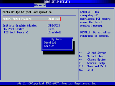
Why does this setting exist? The chipset is capable of remapping RAM that conflicts with PCI MMIO regions to addresses above 4GB; this feature is useful when the operating system supports accessing that RAM, such as a 64-bit operating system or a 32-bit operating system with PAE support. For more information, see here and here.
However, what is less comprehensible is why the default behavior is to unmap RAM between 3GB and 4GB entirely. While it is true that disabling physical addresses that conflict with PCI MMIO regions is more costly than necessary due to poor granularity of the disabled regions, it would seem that allowing the remaining memory to at least be counted and allocated to the extent possible would be a reasonable default behavior. Instead, the system pretends that RAM between 3GB and 4GB does not exist at all. Is there a reason for this? Inquiring minds want to know!
Edit: It appears that enabling this setting remaps the physical region from 2GB-4GB to be addressible starting at 4GB instead (only accessible by a 64-bit OS). With it disabled, the OS will be able to use up to 4GB of RAM that is not covered by PCI MMIO address space. In the case of this system, I had forgotten about the GPU RAM! So with Memory Remap turned off, more than 1GB of PCI address space was overlapping physical memory and rendering it unusable to the system. Mystery solved!
CPU upgrade note
The fastest CPUs available for the P5B-E are the Core 2 Extreme ‘Kentsfield XE’ series. These are quad-core processors with a 130W TDP. The QX6800 and QX6850 are very similar; the only difference is the FSB (1066MHz and 1333MHz respectively). However, the Intel P965 platform limits the FSB to 1066MHz, which makes the QX6800 the fastest available processor for the P5B-E. This processor can now be obtained on eBay for $50 or less.
Another reason the QX6800 is a good choice for the P5B-E is because the clock multiplier is unlocked. The reason this is a beneficial feature in a non-overclocking scenario is a bit obscure.
The Intel P965 chipset does not allow a downward memory multiplier. In effect, this means that the memory cannot run at a slower clock speed than the CPU FSB.
The fastest RAM the P5B-E supports is DDR2-800 (PC2-6400). To use DDR2-800 RAM at 400MHz, the CPU FSB must thus be set at 400MHz (1600MHz).
However, to run a multiplier-locked 1066MHz CPU at a 1600MHz FSB would become more difficult with higher multipliers due to the leveraging effect. If the QX6800 were multiplier-locked, its 11X multiplier would cause it to be clocked at 4.4GHz, which is at the very top end of what is possible on the Core 2 platform. (There are other considerations for scaling the FSB upwards such as the how the manufacturer implemented northbridge strapping: see here and here.)
Fortunately, since the QX6800 is multiplier-unlocked, it can be run at at a close-to-stock 7x or 8x multiplier to yield a 2.8Ghz or 3.2GHz clock speed. This will not require special cooling considerations for the CPU, but will allow DDR2-800 RAM to operate at its rated speed. This would otherwise be impossible with a high-end, multiplier-locked Core 2 CPU!
P5B-E board revision and CPU FSB
There are at least two revisions of the P5B-E mainboard. Rev. 1.02G adds the ability to adjust the northbridge, southbridge, and ICH voltages:

The northbridge voltage is the most important; it is difficult to attain a CPU FSB above 350MHz on the P5B-E without being able to increase the P965 NB Vcore from the default 1.25V, although the very similar P5B has possibly seen some better results. Therefore, if you have a Rev. 1.01G P5B-E, don’t bother trying to increase the CPU FSB beyond 350MHz or so.
At a 350MHz CPU FSB, you have two choices for the RAM speed: 700MHz and 875MHz. If DDR2-800 RAM is not stable at 875MHz, options are to loosen the timings or increase memory voltage. For example, if the memory is rated for 4-4-4-12, try 5-5-5-15 instead. Increasing the memory voltage may help stability, but the tradeoff is greater heat generation; RAM with small heat spreaders is often rated up to 2.1V, and RAM with large heat spreaders can likely tolerate more. If neither of these options result in a stable system, or the system will not boot at all at 875MHz regardless of timings, then the final option is to decrease the RAM clock to 700MHz.
At a 350MHz FSB, the closest CPU multiplier to stock will be 9x, to run the QX6800 at 3.15Ghz. Again, the unlocked multiplier helps here in keeping the CPU close to stock speed, and thereby reducing the number of experimental variables in customizing for maximum speed.
In my case, I was able to initially run the QX6800 (SLACP) at a 320MHz FSB and 10X multiplier (3.2GHz) with air cooling and BIOS automatically-determined voltages. The DDR2-800 RAM was then able to operate at its native speed (at a 4:5 FSB:RAM clock ratio) and 4-4-4-12 timings. Increasing the FSB even to 333MHz began necessitating tradeoffs: the RAM was then nonfunctional at CL4 and had to be bumped to 5-5-5-15 or reduced to a 1:1 FSB:RAM clock ratio to even successfully POST. As for the CPU, an 11X multiplier for the CPU (3.55GHz) proved unstable in memtest86+ under air cooling.
Unfortunately, the G.Skill F2-6400CL4S-1GBPK RAM that came with the system — despite being marked 4-4-4-12 — proved unstable at 4-4-4-12 during kernel compilation, but worked at the SPD default CL5. Increasing the DIMM voltage to 1.9V as indicated on the G.Skill website — but not the DIMM label itself — provided stability sufficient to complete a multicore Linux kernel build. (One point of interest revealed by using decode-dimms to dump the SPD EEPROM data is that the tRC and tRFC timings differ between DIMMs that, while being marked with identical G.Skill model numbers, are via visual differences obviously sourced from different manufacturing batches.) Also, a consistently bad address was found in repeated memtest86+ runs on one of the DIMMs; this was disappointing in terms of quality, but the GRUB_BADRAM configuration to exclude the small bad region saved the day at least.
The P5B-E has at least two minor annoyances in an overclocking configuration. The smaller of these is that depending on various settings, RAM speed is sometimes reported incorrectly by the BIOS: for example, RAM running at DDR2-800 speed will be incorrectly reported as PC2-5300. (Using memtest86+ or a DMI tool will report the correct configured speed.)
The larger annoyance is that to compensate for increasing the CPU FSB speed without running the CPU itself at an infeasibly high speed, it is only possible in the P5B-E BIOS (even the last version 1807) to set a lower fixed multiplier, rather than to set a maximum multiplier. But by setting a fixed multiplier, SpeedStep dynamic clocking is disabled entirely by the BIOS. Not being able to utilize dynamic clocking results in even hotter operation and more power consumption at idle for this already-hot 65nm process CPU. A better option would have been to allow the user to set a maximum multiplier and for the BIOS to regenerate appropriate ACPI _PSS tables.
Alternatively, if it were possible to boot Linux at the minimum CPU speed (perhaps by defaulting to the powersave cpufreq governor), then the maximum speed could be limited through tunables for the ondemand cpufreq governor after boot. Unfortunately, the default governor is a compile-time option and is chosen as performance, at least on Debian kernels, so pursuing this option would necessitate maintaining a locally customized kernel.
initrd hacking
A compromise is available that could allow increasing the FSB clock while leaving SpeedStep enabled, which would normally produce an infeasible top CPU speed. If your system is stable enough at the otherwise-infeasible top CPU speed to at least boot an initrd, the initrd script can immediately replace the cpufreq governor with the powersave governor, which will set the CPU to its minimum speed. After the system is booted, a local init script such as /etc/rc.local can set the maximum stable CPU speed, before once again enabling the ondemand governor as in normal operation.
I made the following modifications to my system to change the governor as early as possible (it does not seem to be possible to change it any earlier, such as in early-boot where CPU microcode is loaded from the initrd):
Create /etc/initramfs-tools/scripts/init-premount/overclock (chmod +x):
#!/bin/sh
# Force all cores to lowest speed as soon as possible during boot
PREREQ=""
prereqs()
{
        echo "$PREREQ"
}

case $1 in
prereqs)
        prereqs
        exit 0
        ;;
esac

. /scripts/functions
# Begin real processing below this line
for cpu_policy in /sys/devices/system/cpu/cpufreq/policy*; do echo 'powersave' > ${cpu_policy}/scaling_governor; done
In /etc/initramfs-tools/modules:
# List of modules that you want to include in your initramfs.
#
# Syntax:  module_name [args ...]
#
# You must run update-initramfs(8) to effect this change.
#
# Examples:
#
# raid1
# sd_mod
cpufreq_powersave
Create /etc/default/cpufrequtils:
GOVERNOR="powersave"In /etc/rc.local (add this later after successfully booting at least once):
for cpu_policy in /sys/devices/system/cpu/cpufreq/policy*; do echo 3000 > ${cpu_policy}/scaling_max_freq; echo 'ondemand' > ${cpu_policy}/scaling_governor; doneAnd then finally, update the initrd:
# update-initramfs -k all -uUnfortunately, the results were pathetic. Above 300MHz FSB, Linux would not even completely boot through the initrd, regardless of CPU or FSB voltage settings. Between 280MHz and 300MHz, the initrd would finish, effectively removing the CPU as an experimental variable. However, Linux would crash as the normal system init scripts were running, indicating a remaining problem with the FSB clock. Only once the FSB clock was lowered to 280MHz could I successfully compile a kernel. The QX6800 CPU itself had no problem operating at 3.2GHz there, but without the ability to increase the northbridge voltage, it was impossible to get system stability above 280MHz FSB. Unfortunately, lowering the FSB this low also meant the RAM clock would be lowered with it in a massive tradeoff, since the RAM could not operate at any higher FSB:RAM clock multiplier. The result was that a kernel compilation in the overclocked configuration was only 4% faster than that in the nominal configuration, making this all mostly a mental exercise.
Conclusion
In the end, I left the CPU at the default 266MHz FSB so that SpeedStep could be utilized; I used a 2:3 FSB:RAM clock ratio to run the RAM at DDR2-800 speed; and set the RAM timings to 4-4-4-12 and the DIMM voltage to 1.9V. Trying to squeeze any more performance from the CPU and increasing the FSB speed both involved unacceptable tradeoffs.
Notes on upgrading system with Asus M3A rev 1.x motherboard
April 20th, 2017The Asus M3A 1.xx (not to be confused with the M3A-H) is a decent Socket AM2+ motherboard. Despite being dated (having been released in 2007), it’s still part of a usable — if trailing-edge — desktop system today. The main limitations are DDR2 RAM, SATA II, PCIe 2.0, HyperTransport 3.0, and those of the Phenom CPU platform itself. Here is a small guide for upgrading this system to the maximum.
Google Cast extension stopped working in the Chromium web browser (Sept. 2016)
October 6th, 2016The Google Cast extension for Chrome and related browsers (such as the open source Chromium) allows, like the similarly named Android app, arbitrary desktop content to be mirrored to a HDMI TV or monitor with a connected Chromecast device.
In recent versions of the official Google Chrome browser (version 51 and newer), the Cast functionality has been integrated into the browser such that no extension is necessary, through what is called the Media Router feature.
In a total coincidence, many users of the open source Chromium browser have had problems recently with the Google Cast extension no longer functioning. While initially it appeared to be a deliberate policy change thanks to a Google support channel miscommunication, it turns out that there are two separate issues that could be the cause of the Google Cast extension no longer working in the Chromium browser.
Conflict with new “Media Router” functionality
While the Chromium browser does not seem to have the required functionality to use the Chromecast via the Media Router feature built in, strangely it ships with the associated feature control flag enabled by default, which then prevents the traditional Google Cast extension from working. Simply follow the instructions posted by users in reviews on the Chrome Web Store:
What resolved the issue for me was going to chrome://flags/#media-router and disabling the Media Router from the drop down menu. Then relaunch the browser.
A bug introduced circa Chrome 53-54
A bug was introduced that blocked the Google Cast extension via an error in the content security policy. That bug was fixed on Sept. 20, 2016 and is not present in newer builds of Chrome 54 and onward.
So if you’ve found yourself suddenly unable to use your Chromecast via the Chromium browser: check your configuration flags, upgrade your browser if necessary, and you should be Chromecasting again in no time!
Addendum
The multicast network protocol that Chromecast clients use to communicate with the device is described well in this Cisco manual.
If you are wondering whether your Google Cast extension is working at a basic level (that it is attempting to communicate with the Chromecast(s) on your network), you can do:
# tcpdump -A -i wlan0 -n udp dst 239.255.255.250You should see DIAL protocol packets like the following originating from the IP address where the browser with the Cast extension is running:
16:08:30.400846 IP 172.16.2.24.58274 > 239.255.255.250.1900: UDP, length 172
E.....@...H............l....M-SEARCH * HTTP/1.1
HOST: 239.255.255.250:1900
MAN: "ssdp:discover"
MX: 1
ST: urn:dial-multiscreen-org:service:dial:1
USER-AGENT: Google Chrome/53.0.2785.143 Linux
If you see these packets, the cast functionality in your browser is working and you’ve likely got a different problem on your network.
Micro-Star MS-6167 Rev 1.00 Motherboard Re-cap From Hell
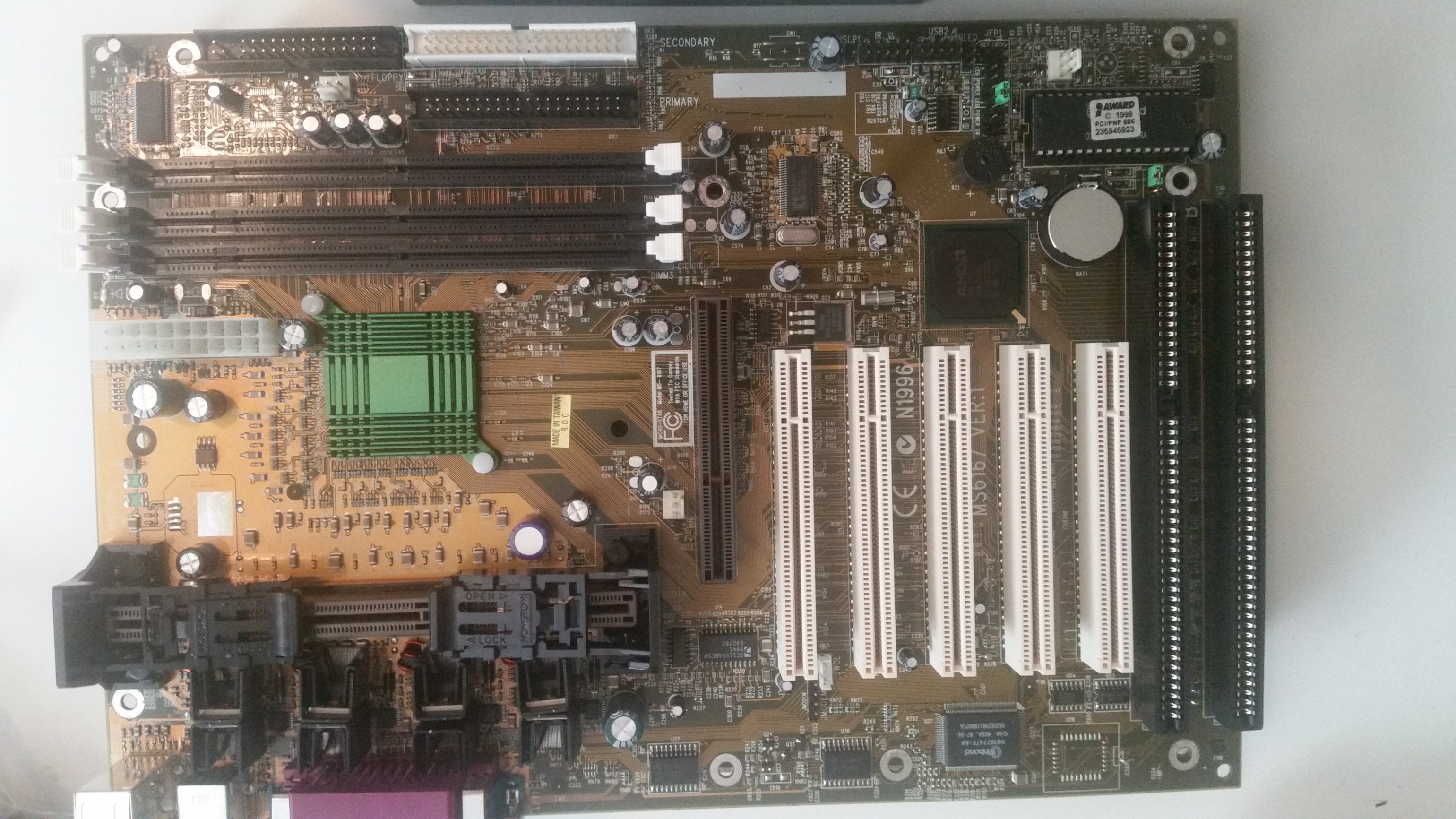
August 21st, 2016This Athlon motherboard was suffering from a leaked 1000uF 10V “Chhsi” capacitor, part of the Taiwanese capacitor plague, and the system was experiencing instability, so I decided to replace it. As usual, when replacing one failed capacitor of a manufacturer and vintage, I sought to replace all such capacitors on this board. However, the end result of this process was a short circuit that caused an IR S14410 power MOSFET near the CPU slot to shoot flames on powerup. What happened?
I found that in (sloppily) replacing a 220uF electrolytic capacitor next to the CPU socket, the via for its negative leg, which is connected to the output of a EZ1580CM adjustable linear voltage regulator, had become connected to the PCB ground plane. Since the PCB is a 6 layer PCB due to design difficulties with the early AMD Irongate Athlon chipset, such erroneous connections between layers are more probable than usual. This resulted in a dead short from both the regulator and the MOSFET drain to source! The regulator got hot enough to fry, but survived, but the MOSFET smoked immediately.
To note, I have both a rev 1.0 and rev 1.0B of this motherboard (pics below; the rev 1.0 has been recapped already). Both are silk-screened “MS6167 VER:1” in large print, but can actually be distinguished by silk screen at the edge between the CPU slot and RAM; the rev 1.0 reads “16167-100” while the rev 1.0B reads “16167-10B”. There are a few differences, but notably, the EZ1580CM regulator located directly underneath the CPU heatsink has been removed, replaced with a LX8384 part, and relocated to the PCI slot area. I don’t understand exactly what this circuit does; it seems to exist to stabilize the 3.3V rail.

Enough rambling, so how do we fix this mess, a short circuit between PCB layers? Well, there are probably a few ways, but after carefully studying the situation and comparing voltages and impedances at various points with the known good board, here’s what I did:
- Removed the (new) 220uF capacitor.
- Drilled out the via causing the short circuit, first with a 1/16″ bit, and when that proved insufficient to clear the short, a 5/64″ bit.
- Once the short was cleared, using hot air I removed the blown MOSFET and added a great deal of solder to the “tab” of the EZ1580CM. The tab carries the output voltage and heatsinks the regulator to the board. By heating up this IC and adding a blob of solder to the top of the tab, I created a connection point for the capacitor leg.
- I then soldered a new 220uF capacitor back in, connecting the leg that would have gone through the (now non-existent) via to the solder blob at the top of the EZ1580CM.
- After a quick check for soldering shorts, I applied power and ensured that the output voltage of the EZ1580CM looked sane (and that the IC was no longer frying). It was about 3.5V. I checked that this voltage was present at the MOSFET source pads.
- I installed a new IR S14410 MOSFET using hot air.
- I powered on the system and it began to act normally again. Success!
This is a lesson in how things can go wrong when I extend my mission to “preventative maintenance” instead of being satisfied with just fixing what’s broke.
Linux SSD TRIM Trivia
July 31st, 2016Enabling SSD TRIM support on Linux can be interesting due to the many storage layers involved. TRIM must be enabled by enabling the relevant discard option at least at the following levels (if they exist in a configuration):
- mdraid (manually in the case of RAID4/5/6)
- dm-crypt
- LVM
Additionally, the filesystem must either be configured with the discard to issue TRIM commands automatically after filesystem operations that clear blocks, or a scheduled fstrim must be performed during a maintenance window. With frequently LVM operations, discard-everything may be a better choice.
But generally, if a device supports queued TRIM and the implementation is not broken in the SSD firmware, then enabling at the filesystem level as well should be a reasonable approach.
To set up a new SSD in Linux, generally Debian’s SSD Optimization wiki is a good place to start.
Here are some questions about interesting TRIM scenarios that I determined the answers to.
Linux hybrid mdraid, mixing SSD and HDD devices
Can a hybrid RAID be trimmed by the filesystem running on top of it? The long and short answer to this question is: actually, this works fine. The TRIM command is sent only to hardware devices which advertise support for it, so it won’t be sent to the HDD. If trimming the filesystem causes errors, check for TRIM support in other intermediate layers (LVM, dm-crypt, mdraid).
Linux software RAID4/5/6
The raid456 driver cannot apparently automatically query the underlying storage layers to determine whether the device zeroes data blocks that have been discarded, and failing to do this is considered unsafe.
So one must check manually the SSD devices using lsblk -D for this feature, which is blacklisted for some buggy hardware:
valhalla:~# lsblk -D
NAME                  DISC-ALN DISC-GRAN DISC-MAX DISC-ZERO
sda                          0      512B       2G         1
??sda1                       0      512B       2G         1
??sda2                       0      512B       2G         1
? ??md0                      0      512B       2G         1
??sda3                       0      512B       2G         1
If the RAID underlying devices (check /proc/mdstat) all have ones in the DISC-ZERO column, it is safe to enable the module parameter:
parm: devices_handle_discard_safely:Set to Y if all devices in each array reliably return zeroes on reads from discarded regions (bool)Which is done by adding raid456.devices_handle_discard_safely=1 to one’s kernel command line in the bootloader configuration.
TRIMming all free space on a disk
Once everything is all set up, one may want to TRIM any unused space in case it was previously written to for whatever reason. This is easy to do as long as an LVM physical volume exists over the entire disk. Simply create a logical volume that uses up all the free space, then delete that volume:
lvcreate -l100%FREE -n blkdiscard SSD-VG
lvremove SSD-VG/blkdiscard